• Intelligent 3-Dimensional Adjustment Hydraulic Equipment
  • Intelligent 3-Dimensional Adjustment Hydraulic Equipment
  • Intelligent 3-Dimensional Adjustment Hydraulic Equipment
  • Intelligent 3-Dimensional Adjustment Hydraulic Equipment
  • Intelligent 3-Dimensional Adjustment Hydraulic Equipment
  • Intelligent 3-Dimensional Adjustment Hydraulic Equipment
Intelligent 3-Dimensional Adjustment Hydraulic Equipment
Request a Quote
We will respond to your inquiry within 8 hours
KET-DBTB-3WIntelligent 3-Dimensional Adjustment Hydraulic Equipment

Features: It can accurately control the lifting speed of the jack and realize the synchronous control of the jack.

Uses: It can carry out functions such as heavy-duty weighing, synchronous jacking, synchronous jacking, synchronous landing, synchronous jacking in equal proportions, 3D attitude leveling, and automatic voltage regulation.

Intelligent 3-Dimensional Adjustment Hydraulic Equipment
  • Details
  • Specs
  • Cases
  • Video
  • Related
Back
Product Detail
  • Product overview
  • System composition
  • Component description
  • Electronics briefing
  • System advantages
  • The system adopts hydraulic drive, pressure and displacement closed-loop automatic control to achieve multi-point control, which can carry out heavy-load weighing, synchronous pushing, synchronous jacking, synchronous landing, equal proportional synchronous jacking, 3D attitude leveling, automatic voltage stabilization and other functions.

    The system uses a frequency conversion governor to control the oil pump motor, relying on adjusting the frequency of power supply to change the speed of the motor, so as to achieve the purpose of continuously adjusting the flow of the oil pump.

    In this system, the hydraulic pump station uses a variable frequency speed motor to control the oil pump, and relies on adjusting the frequency of power supply to change the speed of the motor to achieve the purpose of continuously adjusting the flow of the oil pump.

  • The system is composed of 4 pump stations, 4 three-dimensional hydraulic jacks, 4 sets of frequency conversion speed control devices, 16 sets of control valve groups, 4 sets of balance valves, 8 70MPa pressure sensors, electronic control system and 12 sets of displacement sensors.

  • The Z-axis in this system is equipped with 4 jacks. In the upper part of the jack is equipped with an anti-eccentric saddle. Because the bottom surface of the workpiece is not 100% flat, in order to ensure that the jack load is consistent, before the workpiece is jacked up synchronously, the jack should first be evenly in contact with the workpiece, and the point that the jack evenly contacts the workpiece is taken as the benchmark for the synchronous operation of the jack, for this purpose, a fitting function is provided in the system. Start its function before synchronous jacking, the jack rises at the same time, once there is a top contact workpiece, the top will stop rising, until each jack all touches the workpiece, and then each jack is evenly boosted to about 1MPa per jack (the lamination pressure can be set in the interface), then each jack automatically stops, and the point position is used as the zero point of synchronization. Four sets of displacement detection devices are installed at the appropriate position of the control point, and when the hydraulic cylinder moves, the displacement sensor can accurately determine the displacement of the hydraulic cylinder in real time. A pressure sensor is also installed at the cylinder inlet that determines the load on the cylinder. At the same time, it is also equipped with a balance valve, which can ensure that the hydraulic cylinder is in the state of oil inlet speed regulation when it is lifted and lowered, and the balance valve can reliably maintain pressure to ensure that the workpiece will not slide freely, so that the hydraulic cylinder can still be reliably carried in the state of power failure. At the same time, the attitude of the four jacks can be adjusted in the state of unbalanced attitude, and the displacement of the four jacks can be set, and the different displacements will be completed in the same unit time.

    The Y-axis in this system consists of 4 hydraulic lifting jacks. By mounting the displacement sensor in a suitable position, it is possible to adjust the displacement in the direction of the Y axis. The X-axis has 4 hydraulic jacks. The X-axis hydraulic jack is also equipped with a displacement sensor, which can be used to adjust the displacement in the direction of the X-axis.

    The electronic control system is the key to achieving synchronized movements. It is based on the theory of closed-loop control system, which takes the displacement signal of the moving weight as the controlled parameter, and the pressure signal generated by the heavy object in the stress chamber of the hydraulic jack as the reference quantity. These signals are collected by sensors and transmitted to the controller. The controller accepts and processes these signals. When it is found that there is a possibility of out-of-tolerance at a certain control point, the controller sends a signal to let the inverter at the point act, turn off the hydraulic oil pump, so as to limit the rising or falling action of the hydraulic jack at the point. Similarly, when the signal feedback indicates that there is a lag phenomenon at the stopped point, the controller sends a signal to let the inverter at the point act, turn on the hydraulic oil pump, and let the hydraulic jack at the point resume the action of rising or falling. Through these precisely controlled movements between the control points, the whole synchronous control system achieves a synchronization purpose in motion.

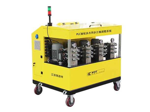
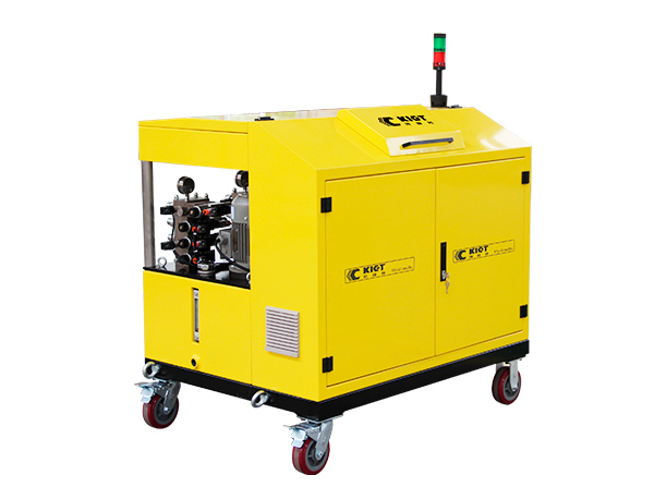
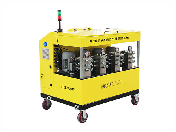
  • The electrical control system is mainly composed of Siemens PLC programmable controller, and the pressure sensor and displacement sensor of each cylinder send the load and displacement signals to the programmable controller. According to the operation instructions sent by the console, the inverter unit is driven, and the output pressure oil makes the corresponding cylinder move. The programmable controller continuously corrects the motion error according to the detected pressure and displacement signals to keep the load of each cylinder synchronized and balanced.

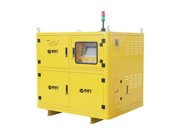
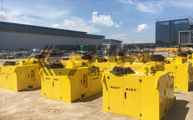
    Complete electrical control system (with later equipment expansion)

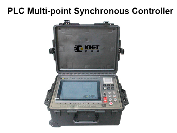
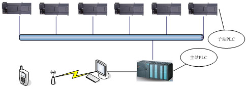
    The control system is mainly composed of a master console, a sub-control box, a communication network, and a sensing system. Its functions are as follows:

    Main control system functions

    ● Read all the pressure values, displacement values and other status values of each substation, and connect the display through the data cable to display the working status of each point in real time;

    ● Send the master control command to each sub-station to realize the overall control of the system;

    ● Calculate the data to ensure the synchronization of each control point of the system;

    Sub-control system function

    ● Read all the pressure values and displacement values of the substation and transmit them to the main console through the bus;

    ● Read the control instructions sent by the master controller, and issue the command to the execution unit;

    Profibus communication technology

    ● PROFIBUS is one of the world's most common fieldbus standards, and has become an important fieldbus standard with its unique technical characteristics, strict certification specifications, open standards, support from many vendors and continuous development of application regulations.


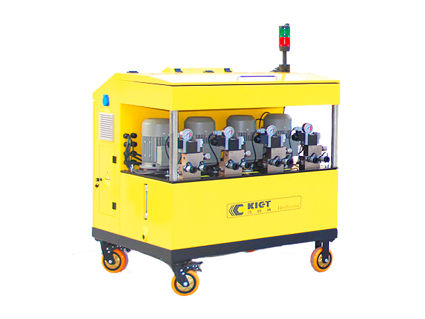
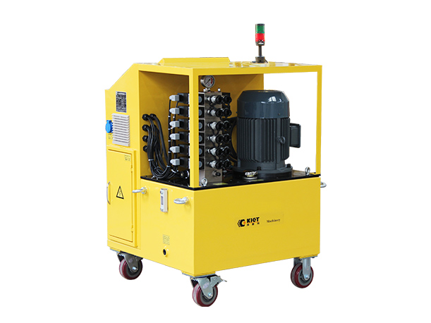
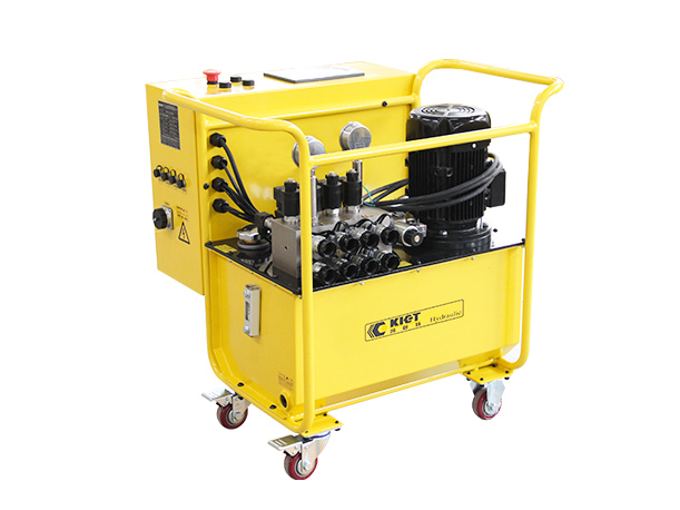
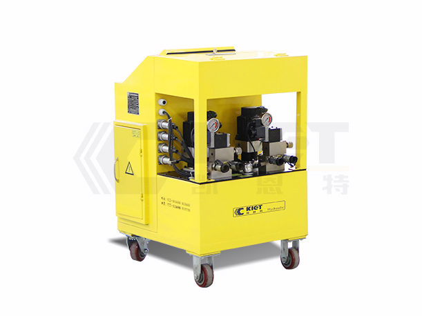
       Electronic control system of the equipment
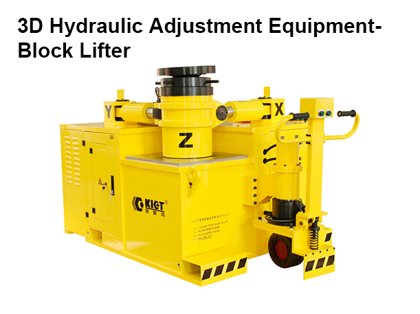
    Sensor system - displacement sensor

    ● The system sensor consists of a jacking direction displacement sensor, a jacking direction pressure sensor, a jacking direction displacement sensor, and a push-out direction pressure sensor. The control system is provided with a sub-controller under each jacked object, which is connected with the main controller through the network bus, and the main controller realizes the centralized control of the whole system, including: the control of jacking and jacking device, the collection of pressure data, displacement data and the alarm of various faults. 

  • ● Continuous flow regulation control, so that the heavy load is stable in the process of jacking and landing;

    ● The hydraulic circuit of oil inlet speed regulation and heavy-load first-drop not only achieves high-precision synchronization during jacking, but also ensures high-precision synchronization when the load is lowered;

    ● The process protection function of the flat-load valve avoids the common expansion accident when multi-cylinder jacking;

    ● It can be extended to 32 points or more on the basis of two-point synchronous jacking, up to 99 points. In the multi-point synchronous working state, in addition to maintaining the synchronization of multi-point positions, the load distribution of each fulcrum can be adjusted according to the user's requirements;

    ● Precise jacking: the dynamometer unit and high-precision displacement sensor that are completely independent of the jack;

    ● Synchronous jacking: dual control of force synchronization and displacement synchronization, which is automatically called at different stages;

    ● Safety: Multiple hydraulic valves and intelligent programs ensure the safety of jacking and data;

    ● Data authenticity: multiple data authority management and: "fool-style" operation to ensure data authenticity;

    ● Controllable and real: the jacking data can be imported into the equipment database at one time, and the data jacking can be called;

    ● Traceability: The jacking results are automatically recorded in the database, which can be consulted, printed and downloaded.

Specs& Dims
Spec Points Synchronization Motor power (KW) Voltage (AC/V) Working pressure (MPa) Flow (L/min) Tank capacity (L) Net weight (Kg) Dimension (mm) (L W H)
KET-DBTB-3W-4A 4 points synchronization  ≤±0.5mm 1.1 X4 380 70 4X1 200 350 1100X875X1460
KET-DBTB-3W-4B 4 points synchronization  ≤±0.5mm 1.1 X4 380 70 4X2 250 430 1200X820X1420
KET-DBTB-3W-4D 4 points synchronization  ≤±0.5mm 1.1 X4 380 70 4X5 500 550 1100X960X1430
KIET Tour
Applications
Videos
Related Product
  • KET-DBTB
    Intelligent Frequency Conversion Control Synchronous Lifting Hydraulic System
    Displacement Synchronization Accuracy::
    ≤±0.2mm
    Display Mode::
    Human-Machine Interface (HMI)
    Simultaneous Control Points::
    2 points, 4 points, 6 points, 8 points
  • KET-SMTB
    Intelligent Control Synchronous Lifting Hydraulic System
    Displacement Synchronization Accuracy::
    ≤±0.5mm
    Display Mode::
    Human-Machine Interface (HMI)
    Synchronous Control Points::
    4 points, 6 points, 8 points, 12 points, 16 points, 24 points, and more
  • KET-LDXT/HDXT
    PLC Multi-point Synchronous Hydraulic Lifting System
    Displacement Synchronization Accuracy::
    ≤±0.5mm
    Display Mode::
    Human-Machine Interface (HMI)
    Simultaneous Control Points::
    4 points, 8 points
  • KET-HZF/XZF
    Intelligent Tensioning Hydraulic Control System
    Displacement Synchronization Accuracy::
    ≤±1mm
    Force Synchronization Tensioning Accuracy::
    0.5%
    Synchronous Control Points::
    4 units, 8 units, 20 units