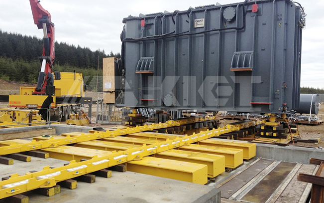
Features: synchronous jacking, clamping rail movement, main transformer dragging system in one.
Uses: Used for installation, maintenance, and transportation of the main transformer of large hydropower stations.
Features: synchronous jacking, clamping rail movement, main transformer dragging system in one.
Uses: Used for installation, maintenance, and transportation of the main transformer of large hydropower stations.
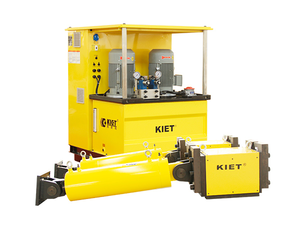
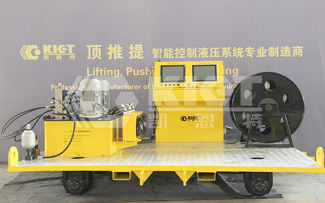
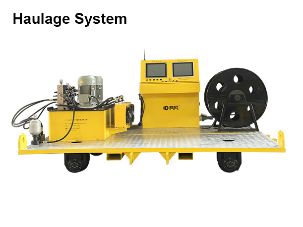
The transformer intelligent transfer hydraulic system integrates functions such as synchronous jacking, autonomous walking, and synchronous pushing. The hydraulic system has the characteristics of high control accuracy, fast system response, good stability and high degree of intelligence.
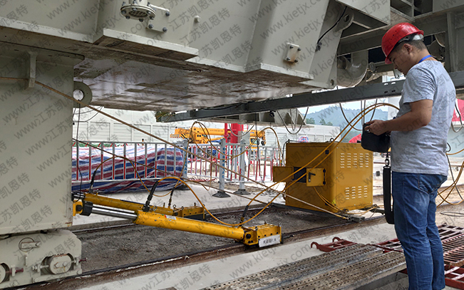
● Synchronous pushing: Move the main transformer out of the station and out of the tooling, and use the rail clamp with push and pull hydraulic cylinder
● Aiming: Due to the main transformer is too close to the surrounding wall, the personnel cannot carry out the construction. Only when the main transformer is moved out of a certain distance can the staff facilitate the operation.
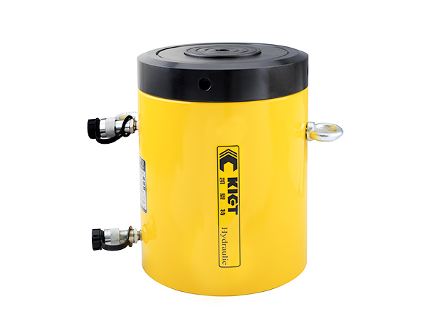
● Synchronous lifting: 4 synchronous lifting hydraulic jacks are installed around the main transformer, once the hydraulic system gets started, adjust the cylinder, synchronous lifting of the jack is well controlled, the main transformer is jacked to the height of the base caster where it can be removed, and the cushion block is placed in the corresponding position as a safety guarantee.
● Dismantle the base caster: the walking wheel which was used previously has now become a burden to the bearing capacity and long-distance walking, so it had got to be removed。
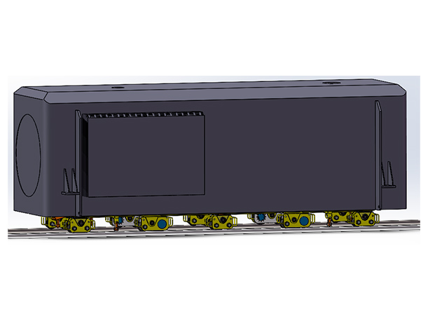
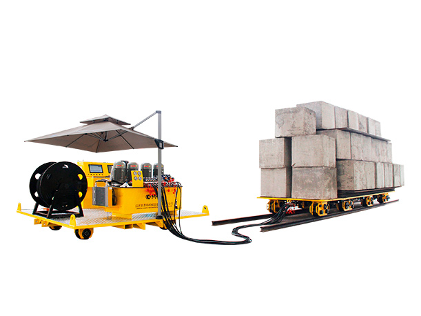
● Walking: Drive the platform trolley into place and descending the jack, let the main transformer fall into the platform trolley, start the walking function, until it has reached to the area where track is changed, the motion stopped.
● Reversing: First, use the synchronous lifting system to stabilize the transformer and start the trolley to support the jack, so that the rim of the walking wheel falls off the track, which is convenient for the caster to change the position. When the rim of the caster stops rising after coming off the track, turn the caster directly above the guide rail perpendicular to the current track and slowly retract the support jack until the power trolley falls steadily on the vertical track. Finally, the synchronous lifting system is launched again and the transformer back on the transport vehicle again.
● two sets of hydraulic rail clamps
● two hydraulic push-pull jacks for rail clamps
● four fixed pins (two long, two short)
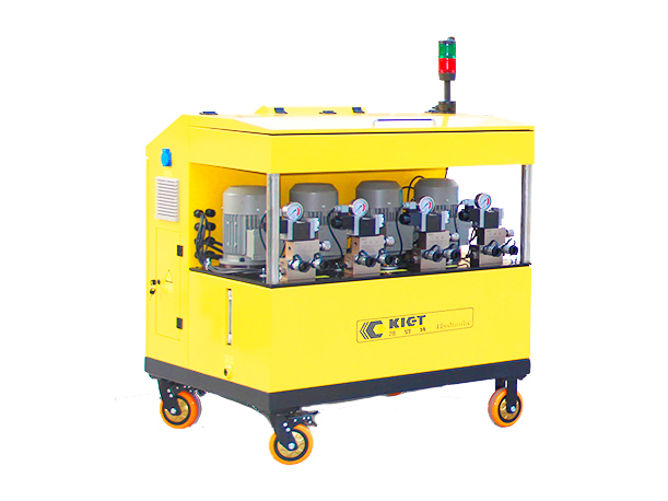
● one hydraulic pump station
● two hydraulic hoses for push-pull jacks
● two hydraulic hoses for rail clamp jacks
● four self-locking hydraulic jacks
● eight hydraulic hoses
● one four-point variable frequency synchronous control hydraulic system
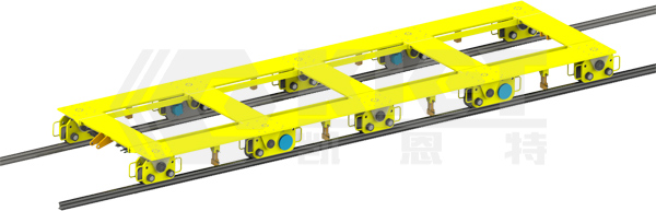
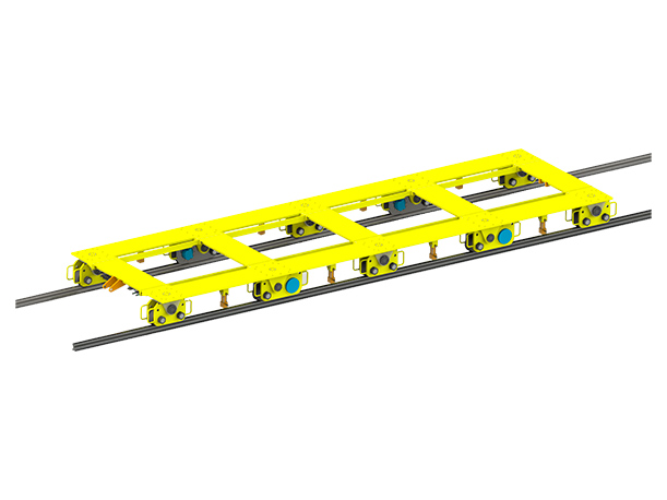
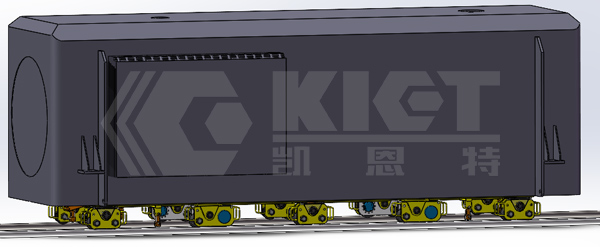
● The powered trolley is equipped with a total of four driving wheel units, six driven wheel units, and platform components.
● The driving wheel units are located in the second group from the left and right at both horizontal ends of the main transformer.
● Four sets of self-locking hydraulic jacks are configured to assist the walking wheels in adjusting direction.
Technical Parameters: